Club Robots 2019 - Planning


#32

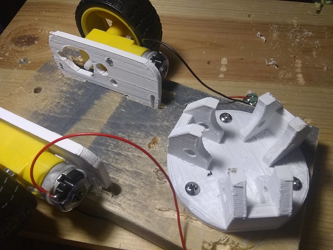
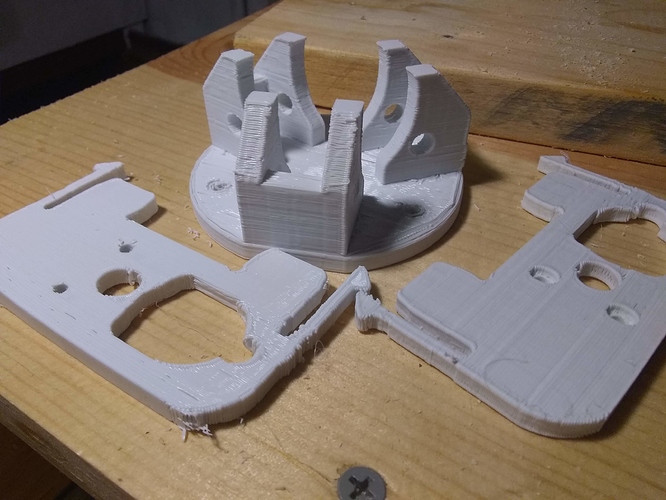
So I tried 3D printing the parts. They work without modification but the clip parts are weak with my poor printer tuning and non-ideal printing orientation. Coincidentally, they work fine with TT motors.

The primary part I was interested in printing, the golf ball caster, printed as one piece acceptably.

You could print these on a better printer with a better tuning and get much better results.

My attempt at making slots was really horrific but works fine as a rough prototype.

I would much prefer the slotted 2D parts as machined parts rather than printed. I don’t think it matters much for the golf ball caster. The main advantage I see from printing the caster is that less assembly is required.

#33

I ordered this pack of SR04 sensors: http://a.co/d/gNLiOHy
I’m going to experiment with them when they arrive. I think I have a way around the voltage level issue and out of range bug at the same time without a level shifter.

Josh, I would consider sensors a vital feature of any robot. I see the WiFi as a nice extra feature that we can afford to lose. I’m more concerned about the I/O imitations because it’s really easy to eat up all the I/O on a controller with sensors and actuators. The other concern I have about 3.3v only is that someone could buy a 5v sensor and expect it to just work out of the box without damaging their chip if they were new to this and forgot about the imitations.

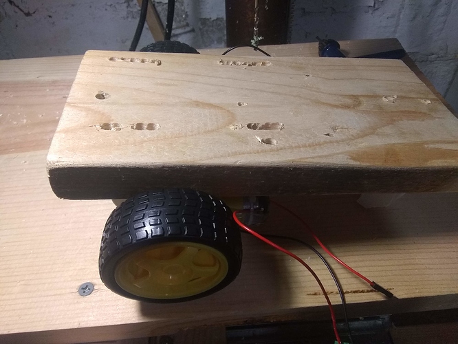
My servos arrived and I’m going to see how well they work on my prototype platform.


#34

Looks like fun with the hot glue gun:grin:

The snaps were designed for 1/2" material. They will not work to retain with 3/4, only as resistance. If you drilled a relief on the top side at the snap, it could allow it to function as designed. I would also print them flat with the “grain” of the printed material oriented along the flex for strength, not perpendicular.

There are slots on one side of the motor mounts that work to capture the nut if you run the screws in from outside. They were sized for M2.5 nuts. Not sure what size you have there or if they would still fit in the printed version.

For the caster bracket, it is interesting to see it, and curious if it fits the ball, but I would make lots of changes to make it a print version. Do you have a ball to test fit?


#35

As I have mentioned before, we should declare the current goal of the robot to define what sensors and the physical build of the base. Future goals would also be great, even if simply wish list, to help choose final configuration and choice between build or buy.

For example, if this goal is to make a wifi remote control, which I thought was the plan, esp12 makes sense. It also gets those that are less capable of programming more interactive from the start. Of course, the programming behind getting them there is far more complicated if they are to actually write the code vs. simply uploading an example. The only suggestion I might make here is to go with the newer esp32 for the massive increase in IO and capability. Of course, the extra $2 per board would be another inflation.

As for 3.3 vs. 5, most new sensors are 3.3v. I personally like 5, but it is a fight against the system to cling to it. You are already having to pay extra for new components that have level shifting built in just to avoid the newer 3.3 normal. Easier to get on board now then double down on the old in my opinion.


#36

I’m a bit confused on our goal at the moment. Are we trying to make a WiFi remote controlled toy or a robot? Right now I’m trying to design a robot with unknown future use in-mind.

I’m fighting to find sensors at 3.3v that I’m interested in using for this robot and at the price point I’m looking for. 3.3v compatible sensors seem more common at higher price points and generally those include level shifting, but even at higher price points the majority of sensors I’m seeing are at 5v.

I’ll still design around 3.3v since that’s the consensus of what we want, but I’m finding it a hassle.


#37

I figured they wouldn’t work well with the thickness, but I wasn’t really planning on testing the snap system as I expect it to work since you’ve had experience with it.

Unfortunately the weakly printed snaps snapped in half. If I was printing for strength, I would have printed them lying flat with 100% infill. For the sake of speed and fitting more parts on the printer, I printed them standing up with 20% infill at the same time as the ball caster. What I need to do is get a magnetic flexible build plate before I print them lying down because otherwise I damage my bed grip material when removing flat parts because of how well flat parts stay on.

I’m using the nut capture as a screw head countersink.

I do not have a ball on hand for testing. I also need to pick up some rollers and associated hardware.


#38

Jason, what’s a good place to get the expanded PVC and what do they list it under?

I’m looking at the Home Depot website and I’m unsure if this is what you use: https://www.homedepot.com/p/1-2-in-x-48-in-x-96-in-White-PVC-Sheet-Panel-190360/205079515

Edit:

I’m also seeing this and it looks similar: https://www.homedepot.com/p/Palight-ProjectPVC-24-in-x-48-in-x-0-236-in-Foam-PVC-Black-Sheet-159845/206402760


#39

For the club, I was going to get it from my scrap material rack.

The material I use is Palight board. That is what was in your second link. Looks like HD only sells 6mm. Not sure about their 1/2" board. I do not buy it from them since they are SUPER expensive and not what I have found to be reliable on stock when I need it.

There are numerous sign and plastic suppliers in St. Louis. Some of them sell direct, but most prefer or only sell to business. They also tend to have minimums that you wouldn’t like for a single part. To keep it simple for the club, my business can be the source.

If you wanted to keep it wood, 1/2" ply should work.

BTW, the wheels on those TT motors are smaller diameter than the wheels I suggested using in my design. They will not match the height of the golf ball without modifying the motor plates.


#40

For my design I want to keep it as mostly off the shelf parts and material sources, so I’m going to stick with wood. I’m giving an exception to 3D printed parts because of the number of people and public places such as libraries with 3D printers. I assume that other club members with 3D printers would be willing to help provide some of the parts if I’m unable to.


#41

Is there an official decision on the short vote?


#42

The official decision is we’d like to go with the custom bases. That is if the MadTooler is willing to use his mad skills to make them.


#43

Finally got a look at the HC-SR04 sensors I ordered. Using this example code on an Arduino Uno: https://howtomechatronics.com/tutorials/arduino/ultrasonic-sensor-hc-sr04/ I have not had any issues with the out-of-range problem. The response time over the serial monitor seems more than fast enough for the speed of robot movement we’re dealing with.

I’ll try them out on the ESP later.


#44

I am starting work on the initial prototype now. Main priority being a functional ball caster. The rest is pretty straight forward.

What I need from the club is any suggested revisions to the design before the next meeting. Primarily with the 1/2" thick main plate’s overall size, shape, possible hole patterns, etc. Any other thoughts are also welcome.

It would also be helpful to hear any thoughts of future projects with these robot bases to better guide any other possible tweaks.


#45

Using the ESP8266 NodeMCU board, the HC-SR04 sensor works just fine with a simple voltage divider. No issues with out-of-range timeouts either.

Given that the sensor is so cheap, I’d recommend including one or two with each kit.

Testing using edges, the sensor stops detecting objects between a 30 to 45 degree angle from parallel with the sensor face. This varies with the axis the angle is on.

My only note on use is that it probably should be avoided being used around pets, so they’re not irritated by it.


#46

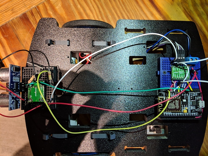
I think we will be mounting to SRF-04 ultrasonic on the front. I think you can probably use self taping screws. we would wither have them side by side off by 15 degrees for left and right detection or have one pointed forward and the other down for front and cliff detection. That could be up to the person building the robot.
On the top a 400 point bread board will be mounted. Might just use double sided tape that is already on the board. We are thinking of including a second smaller 170 point board for optional expansion.
I need some feed back on the batteries. AA for sure. 6 or 9 volt. Would be nice to get a battery pack with a switch to avoid extra parts.


#47

I started a new thread to cover the ball caster:
https://discourse.robomo.club/t/golf-ball-caster/31/3


#48

I made a video of my first attempt at assembling the robot chassis and a test drive using an arduino and IR remote. We should make a better and more complete video after today’s meeting and some hands on time.


#49

Added srf04


#50

where is the code for your range finder version?


#51